This blog will help you understand rotary encoder signals on your drilling equipment and compare what is acceptable in the real world to the textbook pictures published by vendors. Unfortunately, what you see in the real world doesn't look much like the textbooks. This blog will help you determine if your encoder signal is good or bad.
The Encoder Basics from the Books:
Rotary incremental encoders produce a series of pulses. These encoder pulses are used to measure rotation (position) of the shaft, and velocity.
For most quadrature encoders, they produce a set of pre-determined signals.
There are two "channels" of rotary encoder output (A and B in US terminology). The encoder signals are offset from one another by 1/2 of a pulse. Often this is also referred to as 90 degree phase separation. This term comes from discussing one entire encoder pulse cycle, from when the signal first rises up, to where it rises up again as 360 degrees. So you can see that the distance of 1/2 of a encoder pulse would be considered 90 degrees.

So why are there two quadrature channels, and why are they separated by 90 degrees? Simple--the user of the rotary encoder often wants to know the direction of rotation. Encoder manufacturers publish their specification for which signal comes first by specifying the direction of rotation.

Real-World Encoder Signal Troubleshooting
So now let's get to the nitty-gritty of encoder signal debugging. In the real world, lots of bad things happen to the idealized encoder square wave quadrature signal.
Because most encoders lack diagnostics, most customers use an oscilliscope ("scope") to try to debug them. Unfortunately oscilliscopes are not easy to use...we'll discuss in a future blog how oscilliscope settings can confuse the troubleshooter.
Many Avtron encoders offer diagnostics with simple red-green LED output so you don't have to use a scope. Here are some details of the self-diagnostic capabilities:
But many encoder models don't have diagnostics, so let's carry on with our scope. Here's a typical real-world customer picture of nearly ideal encoder quadrature signals (cracked scope screen and all!)

Looks pretty good, doesn't it? The encoder signal waves are square; you can see they are 1/2 a pulse (90 degrees) apart. Now you can see that the tops of the square waves aren't perfect-they have a tiny slope to them. But for an encoder input circuit, no problem. It can clearly see the pulses turning on and off.
Now let's look at some "less ideal" signals:)
Ignoring the optical "flare" on the top of this camera shot from the camera's flash, you can see something that looks like a square wave repeating on the oscilliscope. This was monitoring the encoder's A channel output. Is this good enough for control systems? Is this encoder good or bad?

This rotary encoder signal has 2 important differences from a perfect square wave. First, it has overshoot, where the signal is actually going past the normal supply voltage limits (in this case the signal is going below the low end of the supply voltage, perhaps below 0 volts)
Take a look at the magnified picture below.

This encoder signal isn't ideal, is it? It has that funny "tail" above and below the line that we expected. This is encoder signal overshoot. The good news is that most encoder input circuits ignore or "clip" overshoot. So this is ok for 99% of applications (as long as you wire both A, A/, B, B/). For single-ended wiring applications (A and B only) this is NOT ok.
Let's look at the other side of the encoder wave form closely to debug it:

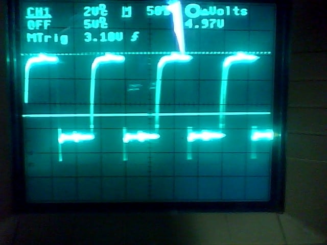
This quadrature encoder signal isn't ideal either. It has a curve instead of the line that we expected. This is encoder signal undershoot. The encoder line driver just isn't powerful enough to create a square pulse. This can be a problem, especially when it gets worse:

Now we have deep problems--the encoder line driver cannot successfully make square waves on the cable, and we don't have square wave quadrature encoder pulses any more. These are not acceptable quadrature encoder signals for most drives and PLCs. The problem here is the low-power line driver.
Interested in eliminating these kinds of encoder signal problems from your drilling rig?
Download our white papers on eliminating rotary encoder failures:

